Computer Parts (Automation)
- 4-bit register
- Edge counter (use as a clock)
- 8-bit multiplexer
- 8-bit de-multiplexer
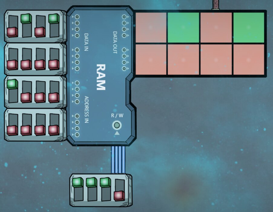
- 8-bit addressable memory module (read gated, so you can combine them to add memory)
- (NEW) 4-bit FULLY programmable logic gate (ROM / PLC)
- (NEW) 8-bit stack-based ALU (16 instructions: 4 stack control, 4 arithmetic, 4 bitwise logic, 4 special)
Uses a 4-bit opcode:
More detail about the opcodes are available here [github.com].
00 – data / stack
0000 – 0 – standby – (do nothing)
0001 – 1 – peek – (send top of stack to data out)
0010 – 2 – pop – (drop) discard top of stack
0011 – 3 – push – (push data in to top of stack)
01 – special
0100 – 4 – increment – increment top of stack
0101 – 5 – swap – swap top and next (might change)
0110 – 6 – copyfrom – copy from stack index (if 0, returns the current size of the stack)
0111 – 7 – reserved – undecided
10 – arithmetic
1000 – 8 – add – pop and add
1001 – 9 – subtract – pop and subtract
1010 – A – multiply – pop and multiply (pushes high bits on stack first, then low bits)
1011 – B – divide – pop and divide/mod (pushes result on stack first, then remainder (modulus))
11 – bitwise logic
1100 – C – or – pop and or
1101 – D – and – pop and and
1110 – E – xor – pop and xor
1111 – F – xnor – pop and xnor
Using the sidescreen, you can map each different possible ribbon input signal to a ribbon output signal.
NOTE: You can also attach a wire to the output, in which case only the first output bit is used. (If you set any of the other output bits to green, the wire will get overload damage.)
Stores 4 bits of binary data from a ribbon.
Has 2 control ports:
- Write – Updates the stored value with the value from the input.
- Read – Sends the stored value to the output.
Writes happen before reads, so if both control ports are on, there is no delay.
The "Read Enable" port is so that multiple registers can share the same output ribbon, but you can choose which one will output to it (e.g. by using a demultiplexer).
Disconnected control ports are treated as "on" (green), so depending on which control ports you leave unconnected, it will operate slightly differenly:
- No control ports connected – Just acts as a "diode" (buffer with no delay) for a ribbon.
- Only read control connected – The "Read Enable" gate controls whether the input signal passes through to the output or not. So it’s a one-way signal gate that you can turn on and off.
- Only write control connected – Acts like a D-flop, but for 4 bits of data instead of just one.
- Both connected – Normal: both write-gating and read-gating; a read-gated D-flop.
Counts the number of times the input signal changes and outputs that in binary to a ribbon.
Connect the output port of the Mux to the input port of the DeMux.
Then attach the output of the Edge Counter to the control ports on each.
The Mux will send one bit per tick of the counter to the DeMux
In 8 ticks of the counter, the DeMux will refresh its output, and it will match the input of the Mux.
The DeMux refreshes when the highest bit on the Edge Counter output changes.
You can string them together to e.g. send 32-bits at a time over a ribbon.
Connect data in and address in to the left side, data out to the right side.
Connect a control ribbon to the R / W port.
- The first bit on the control ribbon is the "read enable" signal; it copies the stored value to the output.
- The second bit on the control ribbon is the "write enable" signal; it copies the input to the stored value.
- The third bit on the control ribbon is ignored.
- The fourth bit on the control ribbon is ignored.
The write enable and read enable bits allow multiple modules to share the same input and output bus, without interfering with each other.
- 8-bit instruction decoder (I already have an instruction set designed that uses the above parts.)
With these additional parts, you should be able to build a fully programmable computer in ONI.
(The stack-based ALU can be used as an instruction sequencer and call stack, as a register, as an ALU, etc. The instruction decoder takes an 8-bit instruction and converts it into two sequential sets of 16 control bits (which determine read channels, write channels, predication, stack pushes and pops, etc. The ROM is where you write the program. I/O with sensors and actuators I’m imagining being memory-mapped, statically.)
Source code available here [github.com].

